Configuration Overview
The following is brief description of the router configuration in this lab. This is still work in-progress and more detail will be added later. Please consult the router documentation for more information.
Note: This lab uses Release 21.11, which is not the latest but the container size is smaller.
Main Lab Topology
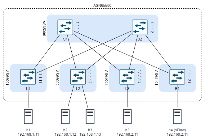
The main clab configuration file creates a Data Centre fabric using BGP, EVPN, and VxLAN technologies. Here is a description of the overall topology:
- The DC consists of two spine switches, three leaf switches, and one border switch.
- There are five servers connected to the leaf switches as follows:
- Server1 is connected to Leaf1
- Server2 and Server3 are connected to Leaf2
- Server4 is connected to Leaf3
- Server5 is connected to Border1
- Servers 1 to 3 reside on the same subnet and the need to communicate at layer 2
- Server4 and Server5 are on separate subnets
- Server5 is designated as an sFlow server. Information about its usage will be added to the documentation later.
The goal of the configuration is to allow connectivity among all servers over the DC fabric.

Configuration Workflow
The following is the description of the configuration procedure. The procedure is divided into three stages:
- Fabric Configuration
- EVPN Configuration
- VxLAN Configuration
Notes:
- The bgp-evpn configuration is not possible on network-instance of type default.
- the system0 interface can only be associated with network-instance default
Fabric Configuration
Prior to configuring EVPN based overlay, a routing protocol needs to be deployed in the fabric to advertise the reachability of all the leaf VXLAN Termination End Point (VTEP) addresses throughout the IP fabric.
Therefore, we need to configure BGP between five autonomous systems (AS). One AS includes the spine switches. Each of the other ASs includes one leaf or border switch. The purpose of configure eBGP is to create an underlay infrastructure that share all system0 (loopback) IP addresses that will be used later.
The configuration includes the following steps (order is not import as long as all steps are completed before committing the configuration):
-
Define the system0.0 interface and assign an IPv4 address:
Switch system0.0 IPv4 Address S1 1.1.1.1 S2 1.1.1.2 L1 1.1.1.11 L2 1.1.1.12 L3 1.1.1.13 B1 1.1.1.21 -
Define the network interfaces for inter-switch links and assigning a /30 IP address to each:
Link IPv4 Subnet S1 – L1 10.10.10.0/24 S1 – L2 10.10.10.4/24 S1 – L4 10.10.10.8/24 S1 – B1 10.10.10.100/24 S2 – L1 10.10.10.12/24 S2 – L2 10.10.10.16/24 S2 – L4 10.10.10.20/24 S2 – B1 10.10.10.104/24 - Define the default network instance and add the system and network interfaces to it.
- Configure a routing policy to allow the exchange of the above addresses.
- Configure BGP:
-
Define the local AS number:
Switch ASN S1 65000 S2 65000 L1 65001 L2 65002 L3 65003 B1 65101 - Define a peer group and assign the local ASN and routing policy to it.
- Define all neighbours
- on leaf switches only, enable ECMP load balancing.
-
At the end of this stage, you should be able to see all BGP neighbours and the advertised routes.
EVPN Configuration
The previous configuration enables us to establish iBGP EVPN sessions between the Leaf and Spine routers. In this stage we create iBGP configuration by including all routers in one AS (65500). The configuration for all routers will be the same but spine will be used also as route reflectors.
Follow these steps in leaf and border switches:
- define a BGP group of type evpn and
- assign it a local AS 65500.
- assign it a transport local-address (use system0.0)
- define the two spine switches as neighbours in the peer group
In the spine switches:
- define a BGP peer-group of type evpn and
- assign it a local AS 65500.
- assign it a transport local-address (use system0.0)
- define rule-reflector
- define all leaf and border switches neighbours in the peer group
VxLAN Configuration
The configuration of VxLAN is different for each router. In summary, we will need:
- Network interfaces to servers connected to the leaf and border routers.
- A VxLAN tunnel in all leaf and border routers.
- A MAC-VRF instance configured in leaf1 and leaf2 to connect the servers attached to these leaves in one broadcast domain.
- An Integrated routing and bridging (irb) interface in leaf1 to allow inter-subnet L3 connectivity.
| Server | IP Address |
|---|---|
| h1 | 192.168.1.11/24 |
| h2 | 192.168.1.12/24 |
| h3 | 192.168.1.13/24 |
| h4 | 192.168.2.11/24 |
| sflow | 192.168.3.11/24 |
Verification and Troubleshooting
Ensure that a BGP session is established:
# /show network-instance default protocols bgp neighbor <neighbor>
To verify the tunnel interface configuration:
# /show tunnel-interface vxlan-interface brief
For the bridge table:
# /show network-instance vrf-1 bridge-table mac-table all
Once configured, the bgp-vpn instance can be checked to have the RT/RD values set:
# /show network-instance vrf-1 protocols bgp-vpn bgp-instance 1
When the BGP-EVPN is configured in the mac-vrf instance, the leafs start to exchange EVPN routes, which we can verify with the following commands:
# /show network-instance default protocols bgp neighbor <neighbor>
The IMET/RT3 routes can be viewed in summary and detailed modes:
# /show network-instance default protocols bgp routes evpn route-type 3 summary
# /show network-instance default protocols bgp routes evpn route-type 3 detail
When the IMET routes from leaf2 are imported for vrf-1 network-instance, the corresponding multicast VXLAN destinations are added and can be checked with the following command:
# show tunnel-interface vxlan1 vxlan-interface 1 bridge-table multicast-destinations destination *
After receiving EVPN routes from the remote leafs with VXLAN encapsulation5, SR Linux creates VXLAN tunnels towards remote VTEP, whose address is received in EVPN IMET routes. The state of a single remote VTEP we have in our lab is shown below from the leaf1 switch.
# /show tunnel vxlan-tunnel all
Once a VTEP is created in the vxlan-tunnel table with a non-zero allocated index6, an entry in the tunnel-table is also created for the tunnel.
# /show network-instance default tunnel-table all
When the leafs exchanged only EVPN IMET routes they build the BUM flooding tree (aka multicast destinations), but unicast destinations are yet unknown, which is checked with the command below:
# show tunnel-interface vxlan1 vxlan-interface 1 bridge-table unicast-destinations destination *
Note: as of the time of this writing, you will be able to ping from h1 to h2 and h3 (on the same subnet) and from h1 to h4 and sFlow server as expected. However, ping from h2 and h3 to severs on remote subnets is not successful. I am still troubleshooting the issue.
Alternative Lab Topology
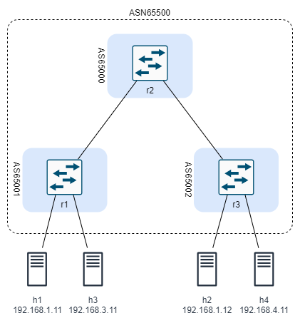
To be able to experiment with srlinux quickly, a smaller topology file is added. The smaller DC topology consists of one spine switch, two leaf switches, and four servers connected to the leaf switches as follows:
- Server1 and Server3 are connected to leaf r1
- Server2 and Server4 are connected to leaf r3
- Server1 and Server2 reside on the same subnet and the need to communicate at layer 2
- Server3 and Server4 are on separate subnets

The goal of the configuration is to allow connectivity among all servers over the DC fabric.
Similar to the main topology, the router are configured to run eBGP to create an underlay infrastructure. EVPN and VxLAN are configured using iBGP as an overlay. Unlike the main topology, route reflector is not needed for this topology.
The IP addresses of the servers:
| Server | IP Address |
|---|---|
| h1 | 192.168.1.11/24 |
| h2 | 192.168.1.12/24 |
| h3 | 192.168.3.11/24 |
| h4 | 192.168.4.11/24 |
Note: as of the time of this writing, you will be able to ping from h1 to h2 (on the same subnet) and from h1 to h3 and h4 as expected. However, ping from h2 to h3 and h4 is not successful. I am still troubleshooting the issue.
References
The above configuration is based on the following tutorials: